
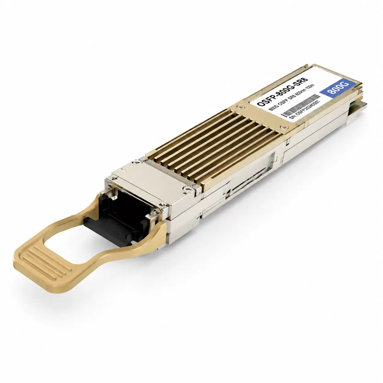
Complete OSFP 800G transceiver portfolio: SR8 (100m MMF), DR8 (500m SMF), DR8+ (2km), 2×FR4 (2km dual CS), LR8 (10km CWDM8), and coherent OSFP. Preferred form factor for AI/ML clusters due to 15W thermal headroom. OSFP vs QSFP-DD800 comparison. ADD Components Hong Kong — full OSFP range.
OSFP Optical Transceiver: 800G Pluggable for AI/ML and Next-Generation Data Centres
The OSFP (Octal Small Form-Factor Pluggable) is an 800-gigabit optical transceiver form factor purpose-built for the thermal and signal-integrity demands of next-generation data centre interconnects. With eight electrical lanes each operating at 100 Gbps PAM4, OSFP delivers an aggregate 800 Gbps in a module that balances port density with superior heat dissipation — up to 15 W of thermal headroom. Originally defined by the OSFP MSA and championed by hyperscale and AI infrastructure operators, OSFP has emerged as the preferred form factor for AI/ML training cluster networking, where sustained high-bandwidth, low-latency optical interconnects are critical to GPU-to-GPU and leaf-to-spine communication. ADD Components supplies the full OSFP 800G transceiver portfolio, pre-coded for compatibility with leading 51.2 Tbps and next-generation switch platforms.
OSFP Architecture: Eight Lanes at 100G PAM4
The OSFP form factor measures approximately 100.4 mm × 22.58 mm × 13.0 mm — slightly larger than the competing QSFP-DD800 (18.35 mm width) but with a critical advantage in thermal management. The module's integrated heat sink — a defining feature of the OSFP mechanical design — provides direct thermal coupling to the host chassis airflow, enabling sustained operation at up to 15 W without the need for cage-mounted heat sinks or additional cooling infrastructure. This thermal headroom is essential for 800G optics, where the combination of eight-channel DSP, eight laser drivers, and eight-channel optical engine can push module power consumption to 12–14 W in DR8 and 2×FR4 configurations.
The electrical interface consists of eight independent 100 Gbps PAM4 lanes, each operating at 53.125 GBd with RS-FEC (544,514) encoding, yielding an aggregate line rate of 850 Gbps (8×106.25 Gbps with FEC overhead) and an effective payload of 800 Gbps. The module connector supports 60-pin SMT contact arrays on both the top and bottom surfaces, providing the signal-integrity performance required to sustain 53.125 GBd PAM4 across the host-to-module electrical channel with acceptable bit-error rates before FEC.
OSFP 800G Variants: Complete Portfolio
| Variant | Data Rate | Lane Config | Wavelength | Reach | Fibre / Connector | Technology |
|---|---|---|---|---|---|---|
| 800G SR8 | 800 Gbps | 8×100G PAM4 | 850 nm (×8) | 60 m (OM3) / 100 m (OM4) | MMF / MPO-16 APC | 8× VCSEL array, DSP |
| 800G DR8 | 800 Gbps | 8×100G PAM4 | 1310 nm (×8) | 500 m | SMF / MPO-16 APC | 8× SiPh or EML array, DSP |
| 800G DR8+ | 800 Gbps | 8×100G PAM4 | 1310 nm (×8) | 2 km | SMF / MPO-16 APC | 8× EML array, DSP, enhanced budget |
| 800G 2×FR4 | 800 Gbps | 2×400G FR4 | CWDM4 (×2 groups) | 2 km | SMF / Dual CS | 2× 400G SiPh CWDM4 engine, DSP |
| 800G LR8 | 800 Gbps | 8×100G PAM4 | 1310 nm (×8), CWDM8 | 10 km | SMF / Duplex LC | 8× EML CWDM8, DSP, SOA (optional) |
| 800G Coherent OSFP | 800 Gbps | Coherent (DP-16QAM or PS) | C-band tunable | 80–1,000+ km | SMF / Duplex LC | Coherent DSP, tunable laser, IC-TROSA |
800G SR8: Short-Reach Multimode for In-Rack and Adjacent-Rack
The 800G SR8 variant employs an eight-channel VCSEL array operating at 850 nm, with each channel modulated at 100 Gbps PAM4. The eight optical signals are carried over eight parallel multimode fibre strands in an MPO-16 APC connector (using the outer 8 fibre positions on each row). Reach is 60 metres on OM3 multimode fibre and 100 metres on OM4, making SR8 the standard solution for ToR-to-server, ToR-to-leaf, and adjacent-rack leaf-to-spine interconnects within a single data hall. The SR8 variant represents the lowest-cost-per-bit 800G solution, leveraging mature VCSEL technology and the existing multimode fibre plant widely deployed in hyperscale data centres.
800G DR8: 500-Metre Parallel Single-Mode
The 800G DR8 shifts to the 1310 nm wavelength window using eight parallel single-mode channels — typically implemented with an eight-channel silicon photonics (SiPh) transmitter optical sub-assembly (TOSA) or an eight-channel EML array. All eight lanes are carried on parallel single-mode fibres terminated with an MPO-16 APC connector, achieving 500 metres — sufficient for spine-to-spine interconnects within large data centre fabrics and cross-aisle leaf-to-spine connections that exceed the 100-metre limit of multimode SR8. An extended DR8+ variant pushes the reach to 2 km for inter-building campus DCI applications.
800G 2×FR4: Wavelength-Multiplexed for Fibre Efficiency
The 800G 2×FR4 takes a fundamentally different architectural approach: instead of eight parallel fibres, it divides the 800 Gbps into two independent 400G FR4 optical engines, each multiplexing four 100 Gbps PAM4 wavelengths in the 1271–1331 nm CWDM4 grid onto a single fibre pair. The two 400G groups are presented on dual CS connectors, enabling two separate 400G connections from a single OSFP module, or a single 800G link when both CS ports are connected. The 2×FR4 variant offers a compelling compromise: 2 km reach (matching the DR8+ envelope) with only four fibre strands consumed instead of sixteen, reducing fibre plant costs in dense fabric deployments.
800G LR8: 10 km CWDM8 for Campus DCI
For links up to 10 km — spanning campus networks, metro connections, and multi-building data centre complexes — the 800G LR8 uses eight 100 Gbps PAM4 wavelengths on an expanded CWDM8 grid, multiplexed onto a single duplex single-mode fibre pair via an integrated multiplexer/demultiplexer. The optical output is presented on a standard duplex LC connector. LR8 modules may incorporate a semiconductor optical amplifier (SOA) in the transmit path to boost launch power and close the 10 km link budget, pushing module power consumption to the upper end of the OSFP thermal envelope at 13–15 W.
800G Coherent OSFP: Pluggable Coherent for DCI
An emerging category, 800G coherent OSFP modules integrate a full coherent DSP, narrow-linewidth C-band tunable laser, and integrated coherent transmitter-receiver optical sub-assembly (IC-TROSA) to deliver 800 Gbps over 80 km to 1,000+ km in amplified DWDM systems. Modulation schemes range from DP-16QAM (200 Gbaud or dual-wavelength) to probabilistic constellation shaping (PCS) for maximising spectral efficiency on long-haul routes. 800G coherent OSFP brings IP-over-DWDM economics to the 800G era, collapsing transponder shelves and enabling 800G router-to-router optical connectivity across metro and regional distances.
OSFP vs. QSFP-DD800: Thermal, Density, and Ecosystem Trade-Offs
| Parameter | OSFP | QSFP-DD800 |
|---|---|---|
| Dimensions (L×W×H) | 100.4 × 22.58 × 13.0 mm | ~121 × 18.35 × 8.5 mm |
| Electrical Lanes | 8 × 100G PAM4 | 8 × 100G PAM4 |
| Max Data Rate | 800 Gbps (1.6 Tbps roadmap) | 800 Gbps (1.6 Tbps roadmap) |
| Thermal Capacity | Up to 15 W (integrated heat sink) | Up to 12 W (cage-dependent cooling) |
| Faceplate Density (1U) | 32 ports (25.6 Tbps) | 36 ports (28.8 Tbps) |
| Primary Adopters | AI/ML hyperscalers, Google, NVIDIA | Enterprise, general-purpose cloud, Cisco, Arista |
| Cage Compatibility | Not compatible with QSFP-DD | Backward compatible with QSFP28/QSFP56 |
The OSFP's defining advantage is thermal headroom: at 15 W, it can comfortably accommodate the power-hungry DSP and optical engines required for coherent, LR8, and future 1.6T OSFP-XD configurations. The integrated heat sink removes reliance on cage-level cooling solutions, which can be inconsistent across different switch chassis designs. The trade-off is marginally lower faceplate density compared to QSFP-DD800 — a sacrifice AI/ML operators accept willingly because their primary constraint is GPU cluster interconnect bandwidth and reliability, not the absolute number of ports per rack unit.
For AI/ML training clusters — particularly those based on NVIDIA Quantum-2/Quantum-X800 InfiniBand or Spectrum-X Ethernet fabrics — OSFP has become the de facto standard. NVIDIA's own switch platforms (Quantum-X800, Spectrum-X800) use native OSFP cages, and the major transceiver ODMs have aligned their 800G product roadmaps around OSFP for the AI networking segment.
Applications
AI/ML Training Cluster Interconnects: The primary deployment scenario. 800G OSFP SR8/DR8 provides the GPU-to-leaf and leaf-to-spine bandwidth required by distributed training workloads across thousands of GPUs, where network bottlenecks directly translate to idle GPU cycles and extended training job completion times.
Hyperscale Data Centre Spine-Leaf Fabrics: 800G DR8 and 2×FR4 provide the spine-to-spine and super-spine interconnect capacity needed in next-generation Clos fabrics built on 51.2 Tbps switch ASICs.
Campus and Metro DCI: 800G LR8 and coherent OSFP extend 800G connectivity beyond the data centre building, supporting campus-scale distributed computing and metro-region data centre replication.
High-Performance Computing (HPC): Scientific computing and HPC interconnects leveraging 800G OSFP to connect supercomputing nodes across multi-rack, multi-row topologies.
Procurement Considerations
Switch Platform Compatibility: OSFP modules require OSFP cages. They cannot be inserted into QSFP-DD or QSFP28 ports. Verify that the target switch platform supports OSFP natively — currently, this is concentrated in the AI/ML networking segment (NVIDIA Spectrum-X/Quantum, some white-box platforms).
Fibre Plant: SR8 requires 8-fibre parallel MMF (MPO-16). DR8 requires 8-fibre parallel SMF (MPO-16). 2×FR4 uses dual CS connectors on SMF. Ensure the structured cabling plant matches the optical variant selected — MPO-16 trunk cables are a prerequisite for SR8 and DR8 deployments.
Power Budget: At 12–15 W per module, 800G OSFP modules contribute meaningfully to switch power consumption. In a 32-port 1U switch, OSFP modules alone can draw 384–480 W. Verify switch PSU capacity and data hall power distribution before deployment.
Roadmap to 1.6T: OSFP-XD (Extra Dense) is the defined 1.6 Tbps successor, supporting 16×100G PAM4 electrical lanes while maintaining mechanical compatibility with the OSFP cage. Organisations planning a 1.6T migration within the switch lifecycle should give preference to OSFP-switch platforms to preserve optics investment.
OSFP represents a deliberate engineering choice: prioritise thermal robustness and signal integrity over absolute port density. For AI/ML infrastructure operators where network performance directly governs the return on multi-million-dollar GPU investments, that trade-off is not merely acceptable — it is the correct design decision. As 800G evolves toward 1.6T, the OSFP form factor's thermal headroom and eight-lane electrical architecture position it as the natural platform for successive generations of AI cluster optics.
Last updated on July 08, 2026